Wednesday, September 16, 2015

Flowchart of Diagnosing and Repair

Computer Repair with Diagnostic Flowcharts Third Edition - PDF Now Available

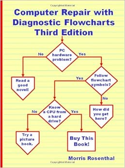
Eight of the troubleshooting flowcharts for PC hardware from my book "Computer Repair with Diagnostic Flowcharts Third Edition" are excerpted on this site and linked below. The non-active links are for charts that are included in the book but not available online. The Third Edition is 170 pages and includes seventeen flowcharts for troubleshooting PCs plus explanatory text for every decision symbol on every flowchart. The troubleshooting process is the same for an expensive Sony or IBM, or a cheaper eMachines or Acer. Dell and HP (who purchased Compaq) manufacture desktop PC's in a wide range of price points, but you have to go through the same troubleshooting steps for the cheap ones as the expensive ones if you want to correctly identify and repair the failure.The PDF eBook is available for instant download or the paperback book can ordered from Amazon for $19.95, or fromAmazon UK for £13.95 or through any retail store by the title "Computer Repair with Diagnostic Flowcharts Third Edition" or ISBN 0972380183. International customers outside of countries served by Amazon will normally get the best price through theBook Depository .
diagnostic flowcharts poster image

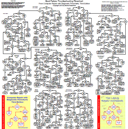
  • Boot Failure Troubleshooting Poster ( 30" x 30" printable PDF). Zoom to 100% after it opens or you'll barely be able to read it! Poster not for sale, but you are authorized to print a copy for personal or classroom use. To print at full size requires an "E" size plotter or a large copy shop printer. My local copy shop charged $7.00 to print a copy.
Computer Repair with Diagnostic Flowcharts Third Edition: Troubleshooting PC Hardware Problems from Boot Failure to Poor Performance, is not for absolute beginners, as you can see from looking at any of the diagnostic charts. There are no photo-illustrations in the book, no history, nor explanations of basic computer part functions, like "What's a hard drive?" The focus of the book is teaching a structured approach to PC repair. The intended audience is hobbyists who already have some experience repairing computers or beginning computer technicians. The book has been adopted as a class text in several technical colleges and vocational training programs. A free evaluation copy is available to instructors of PC repair courses who can demonstrate they are on the faculty of recognized educational institution in the U.S.The PC diagnostics apply to ATX computers, which displaced the old AT standard beginning in the mid-90's. Although I included a few "live power" troubleshooting procedures for advanced techs with their insurance all paid up, the rule for ATX systems is to unplug the power supply before working in the case. The general approach in the diagnostic flowcharts is to try to push parts swapping off until the end, so that readers without a large stock of spare parts will have a chance to fix the problem without spending money. Flowchart critics please note that my main design approach was to avoid crossed lines, which I believe make flowcharts useless.


Computer Hardware Repair & Diagnostic Flowchart
computer repair flowchart

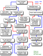
=> My Computer won't even turn on when I press the start button!

=> PC turns on but shuts down right away, or stays on but nothing happens.

=> My computer turns on but fails the POST (Power On Self Test).

=> Unstable Power Supply .

& more...

Computer Repair Flowchart

Hard Drives & Partitions Errors Troubleshoot Flowchart
Hard Drive troubleshoot flowchart

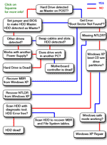
=> No System Disk Found or Boot Partition Errors!

=> Boot Sector Not Found.

=> NTLDR is Missing.

=> Bad Sectors.

& more...

Hard Drive Troubleshoot Flowchart

Motherboard Troubleshoot & Diagnostic Flowchart
Motherboard diagnostic flowchart

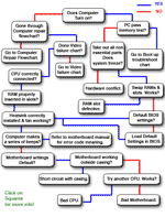
=> Defective RAM.

=> Burned CPU.

=> Hardware Conflict.

=> Bad Adapters.

& more...

Motherboard Troubleshoot Flowchart

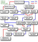
Video Card Troubleshoot Flowchart
Video-card troubleshoot flowchart

=> Nothing on the screen.

=> Wrong Settings, hardware conflicts.

=> Faulty cables.

=> Windows loads only in safe mode

& more...

Video card Troubleshoot Flowchart

Data Recovery
Data Recovery

=> I NEED to Save / Recover my Data!

=> Erased Partition & Data.

=> Hard Drive not spinning up data recovery.

Go to Data Recovery

Windows XP Reset
Windows xp repair

=> No POST (Power On Self Test) error, but my computer won't boot Windows XP
Go to Windows XP Repair

=> Windows XP loads properly, but the system gives errors
Windows XP Restore

=> I prefer to Re-Install Windows XP, as my system is falling apart.
Windows XP Install Guide

Virus, Trojans & other Malwares
viruses and malwares

=> Free Antivirus Scan.
Anti-Virus Scan

=> Free Spyware Scan.
Spyware Scan

=> Free Firewall.
Go to Firewalls

=> Free Registry Scan.
Registry Scanners

Not Sure what the problem is, need a Systematic Hardware Test!
Systematic PC check-up

=> My computer is giving me Errors and crashes not sure why, I need to start with a
Quick Hardware Check

=> I get that famous Blue Screen!
Start with a full Hardware Check

=> I have NO IDEA what is wrong or where to begin!
Begin Here

=> I wish I could just ask someone.
Go to our Computer Repair Forum


Computer Repair Flowchart.

(Computer Repair Tricks, made as easy as 1, 2, 3, computer fixed!)


Welcome to Fixing my computer, theAbsolutely FREE computer repair guide. This site navigates you through a computer repair flowchart with one question at a time.

Fixing my Computer is designed to be as easy and complete as possible. It has two main (interconnected) sections:
Hardware problems (failure) andsoftware problems (including fixing devices & peripherals).

Follow the steps systematically to repair your computer specially in the Hardware section as SAFETY might become an issue.

Fixing my Computer is best suited for Personal Computers (PC) usingWindows Xp. Other computers can also be repaired using this site as a general guide. I do however recommend that you read your user manual first in order to be aware of your hardware specifications.

Can it fix my
computer?

(If nothing is damaged then most probably your computer can be repaired!)


Here are a few of the problems that can be fixed with the computer repair flowchart:

> blue screen problems.

> overheating & cooling solutions.

> OS locked up, password recovery.

> Unbootable systems.

> PC won't start at all.

> Keeps shuting down.

> not responding at all.

> Computer is freezing.

> Virus, worm, spyware, trojans,...

> Boot partition issues.

> Computer hanging & freezing.

> Windows Xp Troubleshoot.

> Devices not found.
     and much more...

Learn about your computer and save money by repairing it yourself!

Repairing a computer is not that technical when you know what the parts do. At first, you'll always need someone with more experience with PC to ask the questions that are tricky. But the most important thing is to learn where to find the right information. The good thing is that you have already started that process and you are already one step closer to get your computer repaired yourself!

Put Safety FIRST always (even when fixing your PC).

Repairing a computer is rather very safe. The only High Voltages is found in the power supply. There are few rules to adhere to, the first one being to use common sense. Make sure you follow this Computer repair guide thoroughly, in order to protect your safety, and hardware parts. The first step is a quick safety review specialized for computer repairs. Do not skip it! It might cost you your health or your computer (or both).

Thin Clients


Thin Clients


thin client (sometimes also called a lean, zero or slim client) is a computer or a computer program that depends heavily on another computer (its server) to fulfill its computational roles. This is different from the traditional fat client, which is a computer designed to take on these roles by itself. The specific roles assumed by the server may vary, from providing data persistence (for example, for diskless nodes) to actual information processing on the client’s behalf.
Thin clients occur as components of a broader computer infrastructure, where many clients share their computations with the same server. As such, thin client infrastructures can be viewed as providing some computing service via several user interfaces. This is desirable in contexts where individual fat clients have much more functionality or power than the infrastructure requires.
Thin-client computing is also a way of easily maintaining computational services at a reduced total cost of ownership.[1]
The most common type of modern thin client is a low-end computer terminal which only provides a graphical user interface – or more recently, in some cases, a web browser – to the end user.

History

Thin clients have their roots in multi-user systems, traditionally mainframes accessed by some sort of terminal computer. As computer graphics matured, these terminals transitioned from providing a command-line interface to a full graphical user interface, as is common on modern advanced thin clients. The prototypical multiuser environment along these lines, Unix, began to support fully graphical X terminals, i.e., devices running display server software, from about 1984. X terminals remained relatively popular even after the arrival of other thin clients in the mid-late 1990s.[citation needed] Modern Unix derivatives like BSD and GNU/Linux continue the tradition of the multi-user, remote display/input session. Typically, X software is not made available on non-X-based thin clients, although no technical reason for this exclusion would prevent it.[citation needed]
Windows NT became capable of multi-user operations primarily through the efforts of Citrix Systems, which repackaged NT 3.5.1 as the multi-user operating system WinFrame in 1995. Microsoft licensed this technology back from Citrix and implemented it into Windows NT 4.0 Terminal Server Edition, under a project codenamed ‘Hydra’. Windows NT then became the basis of Windows 2000 and Windows XP. As of 2011 Microsoft Windows systems support graphical terminals via the Remote Desktop Services component.
The term thin client was coined in 1993 by Tim Negris, VP of Server Marketing at Oracle Corp., while working with company founder Larry Ellison on the launch of Oracle 7. At the time, Oracle wished to differentiate their server oriented software from Microsoft’s desktop oriented products. Ellison subsequently popularized Negris’ buzzword with frequent use in his speeches and interviews about Oracle products.
The term stuck for several reasons. The earlier term ‘graphical terminal’ had been chosen to distinguish such terminals from text-based terminals, and thus put the emphasis heavily on graphics - which became obsolete as a distinguishing characteristic in the 1990s as text-only physical terminals themselves became obsolete, and text-only computer systems (a few of which existed in the 1980s) were no longer manufactured. The term ‘thin client’ also conveys better what was then viewed as the fundamental difference: thin clients can be designed with less expensive hardware, because they have reduced computational workloads.
By the 2010s, however, thin clients were not the only desktop devices for general purpose computing that were ‘thin’ - in the sense of having a small form factor and being relatively inexpensive. The Nettop form factor for desktop PCs was introduced, and nettops could run full feature Windows or Linux; tablets and tablet-laptop hybrids had also entered the market. However, while there was now little size difference, thin clients retained some key advantages over these competitors, such as not needing a local drive. However, ‘thin client’ can be a misnomer for slim form factor computers using flash memory such as compactflashSD card, or permanent flash memory as a hard disc substitute.

Characteristics of thin clients


Single point of failure

The server, in taking on the whole processing load of several clients, forms a single point of failure for those clients. This has both positive and negative aspects. On one hand, the security threat model for the software becomes more focused on the servers. The clients do not run the software; therefore, only a small number of computers (the servers) need to be secured at a software level, rather than securing software installed on every single client computer (although client computers may still require physical security and strong authentication, to prevent unauthorised access, depending on requirements). On the other hand, any denial of service attack against the server will limit the access of many clients. The server software is typically written with virtual machine technology so every client is isolated and a client crash is easily handled and rebooted. The single point of failure can still exist, however. If the server crashes, data loss is possible.


For small networks, this single-point of failure property might be expanded. The hosting server can be integrated with file servers and print servers relevant to its clients. This can simplify the network and its maintenance, but might increase the risk against that server.
In practice, redundancy can be provided both in the form of additional connectivity from server to the network as well as in the servers themselves, using features like RAID, distributed servers (multiple networked servers appearing as one server to the users), clustered filesystems (which allow files to be accessed from multiple servers), VMWare High Availability and Fault Tolerance or Citrix XenApp's load balancing.

Cheap client hardware

While the server must be robust enough to handle several client sessions at once, the clients can be assembled from much cheaper hardware than that of a fat client. Many clients have minimal RAM, some do not even have a hard drive. This reduces the power consumption of those clients, and makes the system marginally scalable, i.e. it is relatively cheap to connect additional client terminals. The thin clients usually have a very low total cost of ownership, but the need for a robust server infrastructure offsets some cost savings. Thin clients also generally use very low power and might not even require cooling fans, but the servers consume high power and almost always require an environmentally controlled air conditioned server room.


Client simplicity


Since the clients are made from low cost hardware with few moving parts, they can operate in more hostile environments than conventional computers. However, they inevitably need a network connection to their server, which must be isolated from such hostile environments. Since thin clients are cheap, they offer a low risk of theft in general, and are easy to replace if stolen or broken. Since they do not have any complicated boot images, the problem of boot image control is centralized to the server.
On the other hand, to achieve this simplicity, thin clients sometimes lag behind thick clients (PC Desktops) in terms of extensibility. For example, if a local software utility or set of device drivers are needed in order to support a locally attached peripheral device (e.g. printer, scanner, biometric security device), the thin client operating system may lack the resources needed to fully integrate the needed dependencies. Modern thin clients attempt to address this limitation via port mapping or USB redirection software. However, these methods cannot address all use case scenarios for the vast number of peripheral types being put to use today.

Slow bitmapped/animated graphics


Thin clients tend to be optimized for use with simple lines, curves, and text, which can be rapidly drawn by the client using predefined stored procedures and cached bitmap data. In this regard, thin clients work well for basic office applications such as spreadsheetsword processingdata entry, and so forth.
However, all thin clients suffer performance problems when large areas of the graphics display must be updated rapidly with high detail bitmap graphics, which may also need to be redrawn several times per second for animation purposes. In a few cases it may be possible to use a video stream that was already previously compressed such as MPEG orH.264 video, but many graphical programs such as photo editors, 3D drawing programs, and animation tools require high detail uncompressed bitmaps to be displayed in order for the software to be used effectively. Graphics rich 3D games can be completely unusable on a thin client unless the updated screen area is kept very small or the overall screen resolution is very low, to reduce the amount of data sent to the client.
In an attempt to reduce network bandwidth, the server may try to compress high detail bitmaps on the fly before sending the data to the client, but this adds latency to the client-server communications, and may reduce user interface responsiveness. Many thin clients offer options to turn off various graphics rich user interface effects in order to increase performance, such as not showing the contents of a window while dragging or not displaying a desktop background.


Tuesday, September 15, 2015

Video Graphics Performance

2015 VGA Charts


Our brand new 2015 VGA charts are designed to do justice to graphics cards between mainstream and the highest end. We will therefore cover entry-level graphics solutions in a different charts set, as comparing these to high-end card makes limited sense. We run as many as 10 selected benchmarks at resolutions of 1920x1080 (Full HD) as well as 3840x2160 (UHD). Both are run at suitable quality settings. The new Charts test system is based on a Core i7-4930K, which we overclock to 4.0 GHz. It runs on an Asus Rampage IV Black Edition motherboard with 32 GB Corsair Dominator Platinum DDR3 2133 memory. Testing also includes our state-of-the-art equipment to track power consumption in great detail and to measure operating noise through calibrated studio microphones as well as the required software. Lastly, we added an efficiency index, which is based on the gaming index (average game performance at Full HD resolution) and the measured power requirement in a gaming loop.


Comparison between INTEL and AMD processor


AMD or Advanced Micro Devices is a company that has been producing semiconductors, microchips, CPUs, motherboards, and other types of computer equipment for the last 40 years. That makes them the second largest company in this sector currently after Intel.
Intel, or the Intel Corporation, was founded a year earlier in 1968. Both companies were incorporated in Valley in the USA, and are leaders in research and development in the field. These multinational companies are also well known for developing production facilities in Asia, such as in Taiwan, China, Malaysia, and Singapore. Nevertheless, it is said their products are in use in every country where PCs are used.
Both AMD and Intel produce mother boards which are the circuitry at the base of all personal computers. AMD and Intel also create CPU or Central Processing Unit chips for the personal computer. While both are in the same industry but are always vying against each other for marketshare and technological changes.
You can compare AMD and Intel processors on Diffen.

Comparison chart


AMD

User Rating (259):
  • current rating is3.72/5
  • 1
  • 2
  • 3
  • 4
  • 5

Intel

User Rating (215):
  • current rating is3.78/5
  • 1
  • 2
  • 3
  • 4
  • 5
Founded19691968HeadquartersSunnyvale, CaliforniaSanta Clara, CaliforniaProductsMicroprocessors, Motherboard chipsets, DTV decoder chips, Handheld media chipsMicroprocessors, Flash memory, Motherboard chipsets, Network interface cards, Bluetooth chipsetsRevenue$5.649 billion in 2006$31.5 billion in 2006Net income$166 million$5 billionEmployees16,71994,100SloganSmarter ChoiceLeap AheadWebsitewww.amd.comwww.intel.comCEOHector RuizPaul S OtelliniStands forAdvanced Micro DevicesIntel CorporationWhat is it?A company that produces CPU chips, motherboards, and other circuitry for personal computers /Windows software.World’s leading manufacturer of CPU chips. Also produces motherboards and other circuitry for personal computers / Windows softwareCompany TypePublicPublicListed onNYSE (AMD)NASDAQ (INTC), SEHK (4335)

Sunday, September 13, 2015

Home


CMOS

BIOS

BIOS is short for Basic Input/Output System. This small program is used to startup the computer and communicate with hardware before an operating system is loaded. BIOS is stored in ROM chips on the mainboard. Some chips contain programs to support basic hardware such as parallel and serial ports, keyboard and the speaker. Another ROM chip, called the CMOS (complementary metal-oxide semiconductor) chip stores information that is subject to change such as time/date, power saving settings, and video adapter, hard drives and other device settings. BIOS settings are applied at every startup. Modern PCs copy the BIOS information to RAM for faster performance, this process is called shadowing.

Here is a picture of a common BIOS CHIP:


CMOS settings can be changed in the CMOS Setup, which can mostly be entered by pressing the DEL or F2 key during startup (depends on manufacturer, other key or key combinations might apply). Some of the most common CMOS settings are described later in this TechNote. Most mainboards have a "CMOS restore to factory defaults"- jumper which allows you to return to the default CMOS settings configured by the manufacturer. This is useful when you cannot access the CMOS Setup because of incorrect CMOS settings or lost CMOS passwords. Make sure the power is completely off when you shorten the jumper.


CMOS Battery
The information contained in the CMOS chip is maintained by a battery. If the battery runs low, the CMOS content will be lost and POST will display a "CMOS invalid" or "CMOS checksum invalid" message. The first symptom for a battery running low is time slowing down and eventually complete loss of date and time. In some cases you might get a boot device error because a boot device such as floppy disk or hard drive can not be located. Almost always the CMOS battery can be replaced very easily. Here is a picture of a common CMOS battery:


BIOS Upgrades

Most modern BIOSs are stored on flash memory, this enables you to upgrade the BIOS software when needed, in some cases this is necessary to support new hardware technologies/devices. Upgrading the BIOS is called flashing, before you do make sure you write down all settings and during the process pray the power won't be interrupted. The BIOS version ID is displayed during startup. Some mainboards allow replacing the BIOS ROM, although this is not done often.


POST
During startup the BIOS also invokes The POST (Power On Self Test), also stored in ROM, a program that runs multiple self-diagnostic routines. When the computer does not pass the POST it will display an error code or message, or generate a beep code through the speaker when display is not functioning. Failing the POST does not always mean the computer will not be able to boot, required devices that need to pass the POST are CPU, RAM, display adapter and boot device, but if the floppy drive is missing the computer can still be able to continue the boot process. The meaning of the beep codes vary depending of the manufacturer mostly they indicate memory, CPU, display and keyboard problems. Most BIOSs beep once to check if the speaker is working or to confirm that the post has passed successfully.
For the exact meaning of beep codes for AMI BIOSs click here and for Phoenix and Award click here.

Although most BIOS manufacturers started using error text messages, some use numeric POST error codes. Some of them are listed below:
POST error codeProbable Cause
1xxMainboard related errors
200-299Memory related errors.
3xxKeyboard related errors
151Real-time clock failure
161BAD CMOS memory
6xxFloppy Disk related errors
1700-xHard drive controller
31xxNetwork Adapter related errors
Click here for a complete list of numeric error codes by IBM.


COMMON CMOS SETTINGS
Printer parallel port—Uni., bi-directional, disable/enable, ECP, EPP

In the CMOS you are able to configure a parallel port to use EPP or ECP. Enhanced Parallel Port and Extended Capabilities Port are both bi-directional standards, operate in 8-bit, and allow data transfer speed of approximately 2 MB/s. Some of the main differences are that ECP supports Direct Memory Access (DMA) and data compression, which enables higher transfer rates. It is also possible to completely disable the parallel port in the BIOS. Most BIOSs allows you to set the DMA channel, when the port mode is set to ECP.
COM/serial port

Most personal computers have 2 serial ports. In the BIOS you can assign COM1/COM2/COM3/COM4 to serial port 1 or 2. Most BIOSs also allow you to set the I/O and IRQ but this is mostly done automatically.


Floppy drives

The floppy drive(s) can be enabled/disabled in the BIOS (e.g. set to Not Installed). The BIOS also allows you to choose the capacity of the media.
- 360 KB 5.25 inch
- 1.2 MB 5.25 inch
- 720 KB 3.5 inch
- 1.44 MB 3.5 inch
- 2.88 MB 3.5 inch
Some BIOSs also allows you to swap A: and B: and disable seeking a floppy disk for a boot sector during startup.
Hard drivesMost modern BIOSs allow automatically detection of disk parameters. These are some of the primary CMOS settings that apply to hard drives (and CD/DVD-ROM drives, etc.), the settings can be individually configured for the primary master and slave device and the secondary master and slave device.

Type
Common disk types are:
- User, User-defined CHS values
- Auto, automatically detects hard disks parameters at every startup.
- 1-46, predefined combinations of CHS values.
- CDROM, used fot atapi CD-ROM drives
- ARMD, used fo atapi ZIP and LS 120 drives.
- DVDROM

SizeDetermines the capacity of the drive.

CHS values
- number of Cylinders
- number of Heads
- number of Sectors

LBA (Large Block Addressing), technologie to overcome the 528 MB limit.

Another common CMOS setting related to hard drives is Boot Sector Virus protection Enabled/Disabled, enabling this will make the BIOS issue a warning message/beep if a write to the boot sector or partition table of a hard disk is attempted.


Memory
Today's motherboards provide too many BIOS settings regarding to memory to discuss here and most are beyond the scope of the exam. CompTIA does mention parity, non-parity in the exam objectives. Parity adds an extra bit (odd or even) to the 8-bit data-string to ensure data integrity in memory modules. Its successor, ECC, provides even better ways to ensure the data integrity by adding information about individual bits.


Boot sequence
This setting is used to determine in which order devices (e.g. CD, floppy or hard disks) the computer should look for a boot sector.


Date/Time
The Date and Time is set in the BIOS, stored in CMOS, maintained by CMOS battery.


Passwords
In most cases a user (startup) password and a supervisor (setup) password can be set in the CMOS. When a Setup password is required the computer will prompt for it when you try to access the BIOS setup. When a Startup password is configured the computer will prompt for it at every startup. The CMOS password can be reset by shortening the "CMOS restore to factory defaults jumper" or by temporarily removing the CMOS battery.


Plug & Play BIOS
Today's BIOSs are PnP-aware. This means they are able to automatically assign resources such as IRQ and DMA to Plug and Play devices. Information about these PnP devices is stored in a separate area of non-volatile CMOS memory, called the ESCD (Extended System Configuration Database). The PnP BIOS and the operating system can both access this area so they can communicate with each other about resource settings assigned to PnP devices and also to non-plug and play devices. For example, when a fixed IRQ is manually assigned to a particular device using Device Manager, Windows will write this information to the ESCD on shutdown preventing the BIOS from assigning the same IRQ to a PnP device at startup. You can also reserve IRQ's for non-plug and play devices in the CMOS setup, this will prevent the BIOS from assigning these reserved resources to PnP devices, a common example is a legacy sound card that needs IRQ 5.


Power Management
Modern mainboards provide ACPI (Advanced Configuration and Power Management Interface) settings such as wake-up, power button function and standby/suspend timers, these are also configured in the CMOS Setup.

Current CMOS related exam objectives for the 2002 A+ Core exam.
1.1 Identify basic terms, concepts, and functions of system modules, including how each module should work during normal operation and during the boot process.Examples of concepts and modules are:
- BIOS
- CMOS

1.8 Identify hardware methods of upgrading system performance, procedures for replacing basic subsystem components, unique components and when to use them.
Content may include the following:
- Upgrading BIOS
- When to upgrade BIOS


2.1 Identify common symptoms and problems associated with each module and how to troubleshoot and isolate the problems.
Content may include the following:
- CMOS
- BIOS

4.4 Identify the purpose of CMOS (Complementary Metal-Oxide Semiconductor), what it contains and how to change its basic parameters.

Example Basic CMOS Settings:
- Printer parallel port—Uni., bi-directional, disable/enable, ECP, EPP
- COM/serial port—memory address, interrupt request, disable
- Floppy drive—enable/disable drive or boot, speed, density
- Hard drive—size and drive type
- Memory—parity, non-parity
- Boot sequence
- Date/Time
- Passwords
- Plug & Play BIOS

Basic Networking

NETWORKING

Networking is connecting two or more devices to allow communication between them with the purpose of sharing information and resources. Examples of these devices are computers, printers, routers, hubs, modems, and PDAs. The information and resources being shared can be anything from MS Office documents and e-mail to printers and fax devices. Internetworking is connecting multiple networks with the purpose of creating one large network. The Internet is the most common example of an internetwork.


Client/server vs 
Peer-to-peer

Most of today's networks use the client/server model. In this model at least one computer acts as a server. Servers hold resources that are accessed over the network by clients. Examples of resources are shared files, e-mail messages and even applications. Another common server is the print server that allows access to network printers.
In a peer-to-peer network model every computer can act as a client and a server at the same time. An example is a network with 4 Windows XP Professional computers in a workgroup using file and print sharing.


LAN/WAN

The terms LAN and WAN mainly refer to the geographical area of the network. LAN is short for Local Area Network and is a high-speed network typically within a building. WAN is short for Wide Area Network and refers to low-speed networks that cover a large distance, for example a network that spans several cities or the entire globe even. The Internet can be considered the largest WAN, but actually consists of many different WANs, which, in turn, include LANs. The connection between LANs in an internetwork is also referred to as a WAN connection, although a network diagram of a WAN often includes the LANs in it.


Private vs Public Networks

Two other terms used to categorize networks are private networks and public networks. A private network is typically within the premises of a corporation and can be accessed only by users working for, or related to, that corporation. A public network Internet can be accessed by multiple individuals and/or corporations, the best example of a public network is again, the Internet.


Media

The physical connection used to transport electrical signals (bits; 1s & 0s) between the network devices is called the media. Examples of network media are copper cabling, fiber optic cabling and infra-red. The most common types of media are outlined later in this TechNote.


Protocols

To be able to communicate with each other, network devices need a common language. The language network devices use is called a protocol. There are many different types of protocols available, and most protocols are actually a suite of several protocols, each with a different function. For example, one protocol allows data transfer between hosts and another can be used to retrieve email from a mail server. Today's most common protocol, TCP/IP, and several older, less common protocols, are described later in this TechNote.


Addressing

If you want to contact somebody by snail-mail or by telephone you need some sort of address. In a telephone network you need to enter a telephone number to reach your intended communication partner. Similar, devices in a network need an address. There are two types of addresses, the first type is configured in software by a network administrator and uses protocols to define the addressing scheme and format, this type is known as network or layer 3addressing. The other type of address that devices in a network use, is most commonly referred to as MAC address; this address is burned into the chip of the physical network interface.


Network Topologies

physical topology depicts how network devices are connected physically, the cabling.
logical topology depicts the route a the signal takes on the network.
Bus - Devices are connected to a central cable, in this type of network both cable ends are terminated.
Star - Devices are connected through a central hub. The hub forms a single-point-of-failure.
Ring - Every device is connected to two other devices, forming a ring.
Mesh - In a full mesh every device in the network is connected to every other device. In reality a partial mesh is often used in backbone environments.

Collisions


A collision indicates that two or more network nodes have tried to access the network simultaneously, and both put a signal on the network cable at the same time which collide with each other. Occasional occurrences are normal and will not affect network performance.


Access Methods


The access method defines how signals are put on the network media.
Carrier Sense Multiple Access with Collision Detection (CSMA/CD)The access method used in Ethernet networks. In so called broadcast networks multiple nodes are attached to the same cable segment. To avoid that nodes on the network transmit traffic simultaneously and their signals collide, they listen to the network to sense if it is currently in use. If a collision does occur, it will be detected and the sender will wait for an amount of time determined by a backoff algorithm.
Carrier Sense Multiple Access with Collision Avoidance (CSMA/CA)The access method used in Wireless networks for example. It is similar to CSMA/CD, but CA means that a node broadcasts a warning it is about to use the network, before it actually starts to transmit data.
Token PassingThis is the access method used in Token Ring and FDDI networks. A token is passed around the network from station to station, when a station does not need to transmit data it passes the token to the next station in the logical ring. A station that receives the token and needs to transmit data seizes the token and sends a data frame, the receiving station marks the data frame as read and passes it forward along the ring to the source station. During this time no other station can transmit data which rules out collisions. The source station releases the token (passing it to the next station) when it receives the data frame and verified it was read.

NETWORK INTERFACE CARDS (NICs)
A Network Interface Card (NIC), typically an expansion card in a computer, is used to connect to the physical network media. Some mainboards and most portable computers are equipped with a built-in (onboard) NIC. NICs are available for different types of network media, the most common today being Ethernet NICs with a RJ-45 socket for UTP/STP cabling. To install a network interface card you need a free ISA or PCI expansion slot and an appropriate driver that the computer's operating system will use to communicate with the NIC. Some older ISA NICs can be manually configured to use a particular IRQ. This is done by setting jumpers or dip switches. Some other NICs allow the IRQ to be configured through the use of configuration software.


An image of a Fast Ethernet network interface card.

Many of today's NICs are equipped with status indicators in the form of leds. These leds can be used to troubleshoot network problems. Typically one green led indicates the NIC is physically connected to the network and flashes when activity occurs, i.e., the port is transmitting or receiving data, this is also known as a heartbeat. When the NIC supports multiple speeds, for example 10 and 100 Mbps, there can be a green led for each speed, of which one is lit indicating the current speed, possibly auto-negotiated with a hub or switch. Some NICs, as well as other network devices such as hubs, include and orange or red led which flashes when collisions occur. If the collision LED flashes repeatedly or continuously, the NIC maybe be configured incorrectly or may be malfunctioning, or there may be other devices utilizing the network heavily.

As described earlier, networks interfaces are physically configured with an address known as the MAC address (MAC is short for Media Access Layer), layer 2 address, Burned In Address (BIA), or physical address. Here's an example of a MAC address: 00-10-E3-42-A8-BC. The first 6 hexadecimal digits specify the vendor/manufacturer of the NIC, the other 6 define the host. MAC addresses are supposedly unique across the planet.

Half duplex vs. Full-duplex communication

Half-duplex means that only one host can communicate at a given time, two hosts communicating with each other will take turns transmitting. In full-duplex communication both hosts can transmit at the same time, in theory allowing twice as much data to be transmitted over the same connection.
The connections able to run at full-duplex are cross-cable connections and connections to a port on a switch, where collisions cannot occur because each end has it's own wire pair (separate segment).


MEDIA
The list below shows some important considerations to make when choosing the proper media for a particular network solution:
CostBesides the high cost of some cable types you also have to consider that the equipment that is used to put the signal on the cable, and take it off the cable, differs a lot in price.
Maximum distanceNetwork media is bound to a maximum cable length, because when a signal travels through the cable it will get weaker.
FlexiblitySome types of media are more flexible than others. Typically, the thinner the cable the easier it is to implement. Except for fiber optic cabling, this has to be placed with care to avoid breaks.
Susceptibility to electrical interferenceSome cables, such as UTP, are more susceptible to nearby high-voltage devices or other sources of electrical interference, than other cables, such as STP or fiber-optics.
Susceptibility to cross-talkCross-talk refers to interference from other data cables.
Susceptibility to fire.Plenum cabling is designed to better withstand the introduction of fire than PVC, and, if burned, generates less smoke toxicity as a result. It is less flexible and it is more expensive. Plenum is typically used in environments such as hospitals.

RS-232

The RS-232 standard specifies serial cabling using DB-9 or DB-25 connectors. The maximum length for a RS-232 cable is 50 feet (15.25 meters) at a baudrate of 19200. The RS-232 standard is designed to supports data transfer rates up to 20 Kbps.


Example of an RS-232 serial cable with a female DB-9 and a male DB-25 connector.


TWISTED PAIR
The most common type of twisted pair cabling is Unshielded Twisted Pair (UTP) cabling. This type of cabling is typically made up of 4 twisted pairs of copper wires as depicted in the image below. Each wire has its own cover, and so does the complete bundle.

UTP cabling is categorized using a number. The required category depends on the network technology and the desired transmission speed. Following are the UTP categories:
Cat.1Used for voice/telephone communication only.
Cat.2Data rates up to 4 Mbps.
Cat.3Data rates up to 4 Mbps in TokenRing networks, 10 Mbps in Ethernet networks, bandwidth of 16 MHz.
Cat.4Data rates up to 16 Mbps in TokenRing networks, 10 Mbps in Ethernet networks, bandwidth of 20 MHz.
Cat.5Data rates up to 100 Mbps, bandwidth of 100 MHz
Cat.5eData rates up to 1 Gbps (Gigabit Ethernet), bandwidth of 100 MHz rated (tested up to 350 Mhz).
Cat.6Data rates up to 1 Gbps (Gigabit Ethernet), bandwidth of 250 MHz rated (tested up to 550 Mhz).
Another, more expensive type of twisted pair cabling is Shielded Twisted Pair (STP). STP cabling includes a metal cover shielding the bundle of wires, reducing electrical interference and cross-talk.

In a cross-over cable wire 1 & 3, and 2 & 6 are crossed, these cables are typically used to connect a pc to pc, or switch to switch for example.

UTP cabling in networks use RJ-45 connector as depicted below:


10BaseT Ethernet, 100BaseTX Fast Ethernet, 1000BaseT and Token Ring are the most common networks that use twisted pair cabling and are described below.

10BaseT
The 10BaseT specification uses Cat 3, 4 and 5 UTP cabling in a star/hierarchical topology. Devices on the network are connected through a central hub.

10BaseT specifications:
- Maximum segment length is 100 meters
- Maximum data transfer speed is 10Mb/s
- Cat 3, 4 and 5 Unshielded Twisted Pair (UTP)

100BaseTX (Fast Ethernet, 802.3u)
Is similar to 10BaseT, except it requires at least Category 5 UTP or Category 1 STP cabling. Only uses 4 of the 8 wires like just like 10BaseT. The maximum data transfer rate is 100 Mb/s.

802.5 (Token Ring)

Token Ring uses the token passing method described earlier in this TechNote. While the logical topology of a Token Ring network is a ring, the physical topology is star/hierarchical as illustrated in the diagram below. Stations connect to MultiStation Access Units (look a bit like hubs) using UTP cabling which in turn are connected in a physical ring. 
Token Ring specifications:
- Data transfer rate is 4 or 16 Mb/s
- Uses Twisted Pair cabling (Cat 3 for 4 MB/s, Cat 5 for 16 Mb/s)
- Logical topology ring, physical topology is star

Token Ring is originally created by IBM, and was later standardized by IEEE under the 802.5 specification. The original IBM Token Ring specification uses IBM Class 1 STP cabling with IBM proprietary connectors. This connector is called the IBM-type Data Connector (IDC) or Universal Data Connector (UDC), and is male nor female.


COAXIAL

Coaxial cabling is used primarily in 10Base2 (Thinnet) and 10Base5 (Thicknet) Ethernet networks. Coaxial cable uses a copper core with a protective shield, to reduce interference. The shield is covered with the outside cover made from PVC or plenum. The most common types are listed in the following table.
RG-58U50 Ohm, used in 10Base2 Ethernet networks (Thinnet).
RG-850 Ohm, used in 10Base5 Ethernet networks (Thicknet).
RG-59 / RG-675 ohms, used for cable television (hence, cable modem access), video, digital audio, and telecommunication applications (for example for E1 coaxial cabling).
10Base2

Commonly referred to as Thinnet, uses a bus topology. Stations are attached using BNC T-connectors represented in the picture below. Both cable ends are terminated using a 50 ohm terminator.


BNC (British Naval Connector) T-connector.

10Base2 specifications:
- Maximum segment length is 185 meters
- Maximum data transfer speed is 10Mb/s
- 0.2 inch, 50 ohm RG-58 coaxial cable (Thinnet) 


10Base5

Commonly referred to as Thicknet, commonly uses a bus topology. Stations are attached to the cable using MAUs, a transceiver that is attached to the cable using vampire taps that pierce the cable. A cable with AUI connectors is used to connect the transceiver to the network interface on for example a computer, hub or repeater. Both cable ends are terminated using a 50 ohm terminator.
AUI connectorsMAU transceiver

10Base5 specifications:
- Maximum segment length is 500 meters
- Maximum data transfer speed is 10Mb/s
- 0.4 inch, 50 ohm coaxial RG-8 cabling (Thicknet)


FIBER OPTIC


Fiber optic cabling is a rather new technology that allows for fast data transfer over large distances.
Fiber optic cabling is not susceptible to electrical interference, but needs expensive equipment and is fragile. There are two main types of fiber optics, the first is multi-mode, which is typically used in corporate networks' backbone. In a multi-mode cable, light travels down the fiber cable in multiple paths. Essentially, the light beam is reflected off the cladding (material surrounding the actual fiber) as it travels down the core. The other type is single-mode, this type is typically used by telephone companies to cover very large distances. In a single-mode cable, light travels thru the cable without interacting with the glass cladding (material surrounding the actual fiber), maintaining signal quality for great distances.

Fiber optic cabling is connected using SC, ST or MIC connectors.
SC connectorsST connectorsMIC connectors

Network technologies that use fiber optic cabling include 100BasesFX and FDDI.


100BaseFX (802.3u)
Similar to 100BaseTX but designed to operate over 2 strands of single-mode or multi-mode fiber cabling. One cable is used to send the other is used for collision detection and receiving. The maximum length of a 100BaseFX link is 400 meters in half-duplex mode, 2000 meters in full-duplex mode. 

- 1000BaseLX, uses multi-mode fiber with a maximum length of 550 meters or single-mode fiber with a maximum length of 5 km
- 1000BaseSX, uses multi-mode fiber with a maximum length of 500 meters

FDDI
Another token-passing network technology is Fiber Distributed Data Interface. FDDI networks are often used as backbones for wide-area networks providing data transfer rates up to 100 Mb/s using fiber media. The use of fiber makes it immune to electrical interference, and allows it to transmit data over greater distances. FDDI provides fault tolerance by using a dual counter-rotating ring configuration, an active primary ring and a secondary ring used for backup.


WIRELESS

Infrared

Infrared (IR) communication is typically used between devices such as PDAs, laptops and printers. An advantage of IR communication is that it is not susceptible to electrical interference. The main disadvantage, besides the rather short maximum supported distance between devices, is that there must be a clear path between the devices. Supports data transfer rates up to 4 Mbps.


802.11b (Wi-fi)

The 802.11b standard specifies wireless Ethernet LAN technology. The topology used in wireless networks is known as cellular. It is a wireless structure where stations send signals to each other via wireless media hubs. The access method for 802.11b is CSMA/CA. Clients connect via wireless access pointswith data transfer rates up to 11 Mbps. 802.11b operates in the 2.4 GHz range. Another WLAN standard that has recently emerged, 802.11a, offers a maximum transmission speed of 54 Mbps at 5 GHz frequency.


NETWORK COMPONENTS
RepeatersUsed to extend the maximum distance a cable segment can span. Repeaters grab the incoming electrical signal from the cable, amplify it, and send it out.
HubsHubs, also known as concentrators or multiport repeaters, are used in star/hierarchical networks to connect multiple stations/cable segments. There are two main types of hubs: passive and active. An active hub takes the incoming frames, amplifies the signal, and forwards it to all other ports, a passive hub simply splits the signal and forwards it.
BridgesUsed to increase network performance by segmenting networks in separate collision domains, or increase the network size. Bridges are not aware of upper-layer protocols such as TCP/IP or IPX/SPX. They keep a table with MAC addresses of all nodes, and on which segment they are located.
SwitchesSimilar to bridges; they also keep a table with MAC addresses per port to make switching decisions. The main difference is that a switch has more ports than a bridge, and instead of interconnecting networks it is typically used to connect hosts and servers like a hub does, but offers dedicated bandwidth per port, hence offers much higher network performance than hubs.
RoutersRouters are used to interconnect multiple (sub-)networks and route information between these networks by choosing an optimal path ("route") to the destination based on addressing information from protocols such as TCP/IP or IPX/SPX. Router are also typically used to connect a LAN to a WAN or another LAN, which can use different technologies such as Token Ring, Ethernet, ISDN, Frame Relay etc.
GatewaysUsed to connect networks with dissimilar technologies, for example a Microsoft TCP/IP network and NetWare IPX/SPX network can be connected using a gateway. Typically implemented in software on a router.
FirewallsProtects a private network from external users, typically those from the Internet, by hiding the internal network and filtering incoming packets. A firewall is not always a hardware device, it can be implemented in software on a router or proxy server as well.


PROTOCOLS

TCP/IP


TCP/IP is today's most popular network protocol and is the protocol in the Internet. It is a routable protocol that provides connection betweenheterogeneous systems, these are the main reasons the protocol is so widely adapted; for example it allows communication between UNIX, Windows, Netware and Mac OS computers spread over multiple interconnected networks. The "TCP/IP protocol" is actually the "TCP/IP suite" composed of many different protocols each with its own functions. The two main protocols are in its name: the Internet Protocol and the Transmission Control Protocol.

IP addressing is assigning a 32-bit logical numeric address to a network device. Every IP address on the network must be unique. An IP address is represented in a dotted decimal format, for example: 159.101.6.8. A
s you can see the address is divided in 4 parts, these parts are called octets.

The current used addressing schema in version 4 of IP is divided in 5 Classes:
ClassesFirst Octet
Class A1126
Class B128191
Class C192223
Class D224239
Class E240254

A subnet mask is used to determine which part is the network part and which is the host part.

Default subnet masks:
Class A255.0.0.0
Class B255.255.0.0
Class C255.255.255.0

IANA reserved 4 address ranges to be used in private networks, these addresses won't appear on the Internet avoiding IP address conflicts:
10.0.0.0 through 10.255.255.255
- 172.16.0.0 through 172.31.255.255
- 192.168.0.0 through 192.168.255.255
- 169.254.0.1 through 169.254.255.254 (reserved for Automatic Private IP Addressing)


IPX/SPX

Although current versions of Novell Netware use TCP/IP, before Netware version 5, IPX was the protocol in Netware networks. It is a small and easy to implement routable protocol developed by Novell and based on the Xerox Network System. The Netware protocol suite is a suite of several protocols for different functions, the most important being IPX and SPX. IPX is similar to the Internet Protocol from the TCP/IP suite, it is a connectionless Layer 3 (Network layer) protocol used to transfer datagrams between hosts and networks. SPX is the Transport protocol used to provide reliable transport for IPX datagrams, similar as TCP does for IP.

The frame types of two Netware hosts must match to enable communication without a router. IPX can use several frame formats, of which the two most important are listed in the following table.
Frame FormatFrame TypeNetware Versions
Novell 802.3 raw802.3Default frame type for Netware 3.11 and earlier. Supports only IPX/SPX as the upper layer protocol
IEEE 802.3802.2Default frame type for Netware 3.12 and 4.x. The main difference with Novell's 802.3 format is the addition of LLC field, which specifies the upper-layer protocol, such as IPX or IP.

An complete IPX network address is 80 bits in length and is represented in a hexadecimal format. As with all routable protocols it needs a network and a host portion, the network portion is 32 bits in length and is manually configured. The host portion is 48 bits in length and is derived from the MAC address of the host's network interface.

Examples of complete IPX internetwork addresses are:
- 0CC001D8.0050.BF61.6C71
- 0000ABBA.0060.9736.954B
- 00000046.0060.E92A.C2A4

NWLINK is Microsoft's implementation of IPX/SPX which allows Windows clients to communicate with Netware servers.


AppleTalk

AppleTalk was developed by Apple Computers in the early 1980s to allow file and printer sharing and mail functionality between Macintosh computers. A Mac that shares resources is called a server, and the computer connecting to it a client. Like TCP/IP, AppleTalk is not just one protocol, but a suite of several protocols for different functions. It is built-in in every Macintosh computer and requires virtually no user interaction, therefore it is very easy to administer in small network environments. Address assignment in AppleTalk networks is automatically. Besides Ethernet and TokenRing, AppleTalk can also be used on Apple's own network technology called LocalTalk, which uses UTP/STP cabling.


NetBEUI/NETBIOS

NETBios Extended User Interface is a non-routable Transport layer protocol. The reason it is non-routable is in its flat addressing schema, NETBEUI usesNetbios names to identify computers on the network that do not contain a network portion. Netbios names are sometimes referred to as friendly names.NetBIOS names are 16 characters in length and cannot contain any of the the following characters: \ / : * ? " < > | The first 15 characters represents a unique name identifying a resource, the 16th character (if you would set a name of 8 characters it is padded with spaces up to 15 characters long to allow a '16th' character) is a suffix identifying the type of resource or group of resources. For example the redirector, server, or messenger services can be installed on one computer resulting in three times the same name but with different suffixes.

NETBEUI is a broadcast protocol, meaning a computer running NETBEUI discovers the MAC address from the intended communication partner by sending out a broadcast with the NETBIOS name. The main advantage of NETBEUI is that it is small in size and easy-configurable.
 
Current related exam objectives for the 2003 A+ Core exam.
DOMAIN 6.0: Basic Networking

6.1 Identify the common types of network cables, their characteristics and connectors.


Cable types include:
- Coaxial
--- RG6
--- RG8
--- RG58
--- RG59
- Plenum/PVC
- UTP
--- CAT3
--- CAT5/e
--- CAT6
- STP
- Fiber
--- Single-mode
--- Multi-mode

Connector types include:
- BNC
- RJ-45
- AUI
- ST/SC
- IDC/UDC

6.2 Identify basic networking concepts including how a network works.
Concepts include:

- Installing and configuring network cards
- Addressing
- Bandwidth
- Status indicators
- Protocols
--- TCP/IP
--- IPX/SPX (NWLINK)
--- AppleTalk
--- NETBEUI/NETBIOS
- Full-duplex, half-duplex
- Cabling—Twisted Pair, Coaxial, Fiber Optic, RS-232
- Networking models
--- Peer-to-peer
--- Client/server
- Infrared
- Wireless

6.3 Identify common technologies available for establishing Internet connectivity and their characteristics.

Technologies include:
- LAN
- DSL
- Cable
- ISDN
- Dial-up
- Satellite
- Wireless

Characteristic include:
- Definition
- Speed
- Connections 


Click here for the complete list of exam objectives.
Current related exam objectives for the 2002 A+ Core exam.
DOMAIN 6.0: Basic Networking

This domain requires knowledge of basic network concepts and terminology, ability to determine whether a computer is networked, knowledge of procedures for swapping and configuring network interface cards, and knowledge of the ramifications of repairs when a computer is networked. The scope of this topic is specific to hardware issues on the desktop and connecting it to a network.

6.1 Identify basic networking concepts, including how a network works and the ramifications of repairs on the network.

Content may include the following:
- Installing and configuring network cards
- Network access
- Full-duplex, half-duplex
- Cabling—Twisted Pair, Coaxial, Fiber Optic, RS-232
- Ways to network a PC
- Physical Network topographies
- Increasing bandwidth
- Loss of data
- Network slowdown
- Infrared
- Hardware protocols